4. Object Oriented Analysis & Design with UML
17/10/22
Unified Modelling Language (UML)
A specification defining a graphical language for visualising, specifying, constructing, and documenting the artefacts of distributed object systems
Advantages
- Enhances communication and ensures the right communication
- Captures the logical software architecture independent of the implementation language
- Helps to manage the complexity
- Enables reuse of design
Object Oriented Analysis
Use Case Diagrams
- They describe a set of actions that some system(s) should or can perform in collaboration with one or more external users of the system or systems.
- No attempt to represent an order or a number of executions.
- Components:
- Actors - Interface with the system, can be people or other systems
- Use cases - Based on user stories, represent what the actor wants your system to do for them
- Subject - Classifier representing a business, software system, physical system or device under analysis
- Relationships - Between use case and actor. Association indicates which actor initiates which use case. Between two use cases
<<inlcude>> - Used when multiple use cases share a piece of same functionality which is placed in a separate use case. Arrow points to the more specific use case
<<extends>> - Used when activities might be performed as part of another activity but are not mandatory for a use case to run successfully.
- Base Path (Optimistic Flow) - Happy day scenario
- Alternative Paths (pragmatic flows) - Every other possible way the system can be (ob)used. Includes perfectly normal alternative use, but also errors and failures
Object Oriented Design
Activity Diagrams
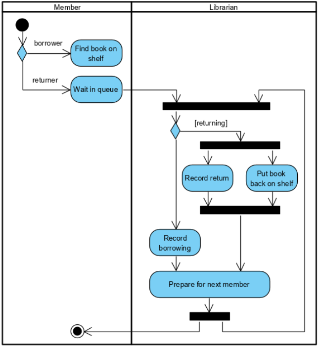
- Graphical representations of workflows of step wise activities and actions related to an individual use case or across many use cases
- Support representation of parallel behaviour

Sequence Diagrams
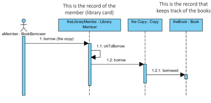
Are a temporal representation of objects and their interactions
Components:
- Participant: Object or actors that act in the sequence diagram
- Vertical line (lifeline): Represent time as seen by the object
- Arrow from senders lifeline to receivers lifeline
- General: Message, denoting an event or the invocation of an operation
- Object creation: Arrow with 'new' written above it
- Object deletion: An X at bottom of lifeline
- Sequence fragment: Let you show loops, branches, and other alternatives

State Machine Diagrams
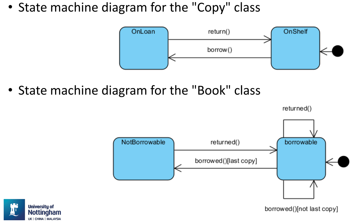
Show the possible states of a single object, the events or messages that cause a transition from one state to another, and the action that result from the state change. Only reactive objects require a state machine diagram!
Components
- State: A condition during the life of an object when it satisfies some condition, performs some action, or waits for an event. Special states:
- Start State: Each state diagram must have one and only one start state
- Stop State: An object can have multiple stop states
- Transition: Denotes the transition between states or to the same state (self-transition)
- Trigger: The cause of the transition (signal, event, passage of time)
- Guard: Condition which must be true in order for the trigger to cause the transition
- Effect: Action invoked directly on the object that owns the state machine as a result of the transition,

Class Diagrams
Shows the existence of classes and their structures and relationship in the logical view of a system
Components
- Classes
- Class relationships; Associations, dependencies, aggregations, compositions, realisations, generalisations
- Multiplicity indicators
Representation
Depicted as rectangles with three compartments:
- Class name
- Attributes: Describe the data contained in an object of the class
- Operations: Define the ways in which objects interact
Other symbols: | | | | --- | --------- | | + | public | | # | protected | | - | private | | / | derived | | $ | static |
Associations between classes - Associated if an instance of class A (source) has to know about an instance of class B (target class) or vice verca
Multiplicity indicators
Number of links between each instance of the source class and targe class | | | | ---- | ------------------------------- | | 1 | exactly 1 | | | unlimited number (zero or more) | | 0.. | zero or more | | 1..* | one or more | | 0..1 | zero or 1 | | 3..7 | specified range (3-7) |
Relationships
Association
- Reference based relationship between two classes

Dependency
- Created when you receive a reference to a class as part of a particular method
- Indicates that you may involve one of the APIs of the received class reference and any modification to that class may break your class as well

Aggregation ("is part of" relationship)
- Same as association and often seen as redundant relationship
- Used when an object logically or physically contains another; the container is called "aggregate"; the components of the aggregate can be shared with others

Composition
- Relates to instance creational responsibility
- When class B is composed by class A, class A instance owns the creation or controls lifetime of instance of class B

Realisation
- Specialised abstraction relationship between two sets of model elements, one representing a specification (the supplier) and the other representing an implementation (the client) of the specification

Generalisation
- Directed relationship between a more general classifier (subclass) and a more specific classifier (subclass)
